
An enclosure passes bench testing, ships, and later develops an EMI problem after transport, maintenance, or several door cycles. Replacing the gasket with the same part might restore performance temporarily, but it does not explain why the shielding path changed. The useful question is not whether the gasket still looks intact. It is where the enclosure seam stopped acting as a single continuous conductor.
Post-install shielding loss is a joint-level failure. The gasket supplies compliant conductive contact, while the enclosure determines how firmly and consistently the surfaces meet. Movement and surface resistance leave one set of clues. Corrosion and loss of material recovery leave another. Reading those patterns lets engineers correct the cause instead of treating every failure as a bad gasket.
Start with the Enclosure Joint, Not the Gasket
An EMI gasket does not shield independently from the enclosure. It closes a conductive path across a seam. A material with strong laboratory attenuation still underperforms when the surrounding joint no longer remains electrically continuous. NASA’s 2022 Mitigating In-Space Charging Effects handbook requires physically and electrically continuous shielded surfaces and warns that unshielded seams, penetrations, and gaps make Faraday-cage implementation incomplete. The handbook addresses spacecraft, but the enclosure principle applies more broadly to gasketed electronics. A post-install failure review should therefore begin at the full seam rather than at the gasket material alone.
The seam behaves as a distributed electrical interface, so a single weak region matters more than the average condition along the perimeter. Contact geometry and local electrical properties change how energy leaks through the joint. A 2025 paper in IEEE Transactions on Electromagnetic Compatibility identified the gasketed seam as a critical factor in enclosure shielding and validated an equivalent modeling approach with experiments. The researchers treated the complex contact surface as part of the shielding behavior rather than an invisible mechanical detail. This result supports a practical rule: locate where continuity changes before deciding which component to replace.
Use the Failure Pattern to Narrow the Cause
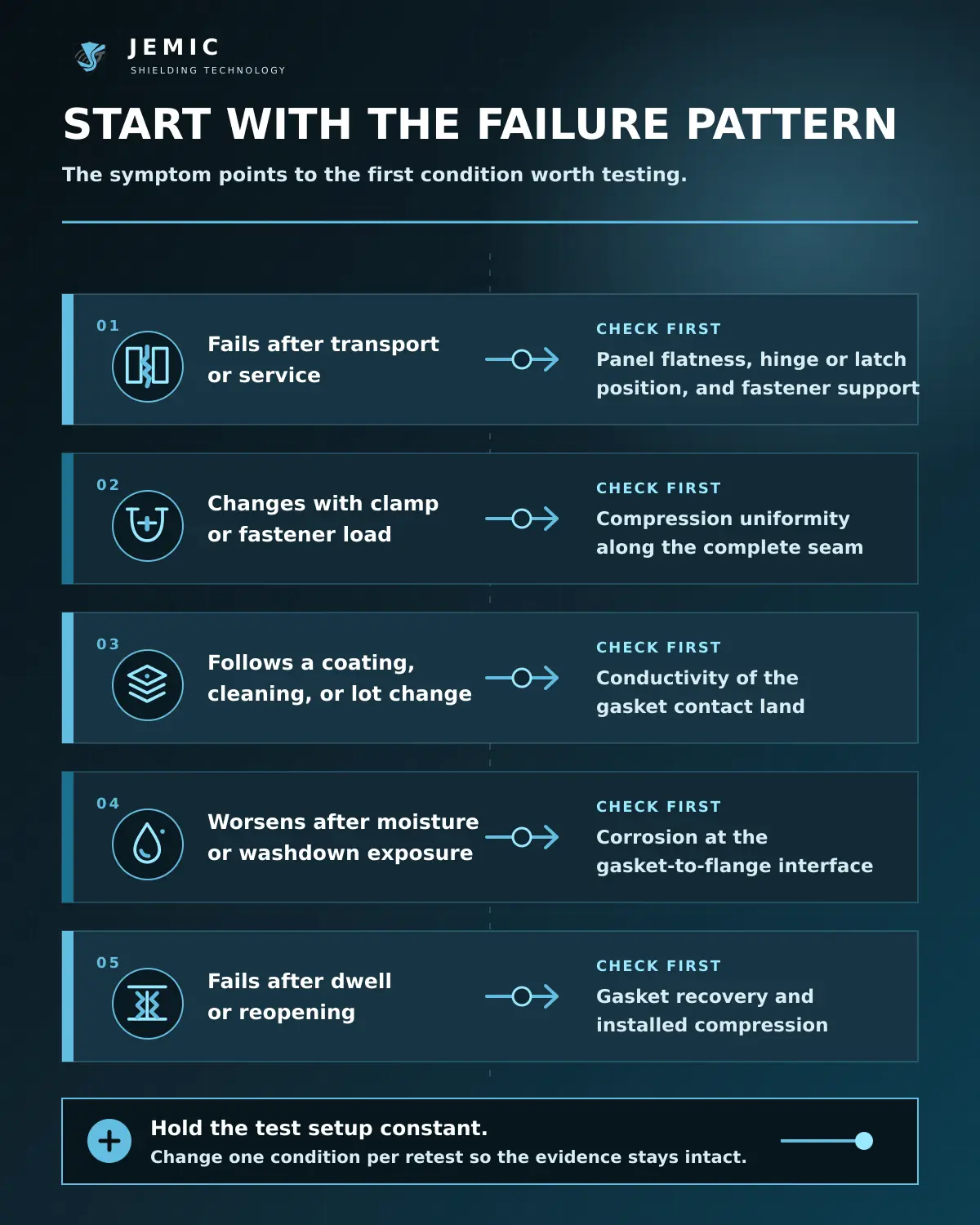
Failure, timing, and repeatability help narrow the search before the enclosure is opened. A problem following handling points toward movement, while a problem tied to humidity points toward interface degradation. A failure responsive to fastener load belongs to a different diagnostic path than one persisting at full closure. Record the pattern under the same test setup used to reproduce the failure.
| Observed pattern | Inspect first | Supporting evidence | Corrective direction |
| Passes at build, then fails after transport or service | Panel flatness, hinge or latch position, and fastener support | A weak contact imprint or gap appears in one region after handling. | Restore the joint geometry, then retest with the original gasket. |
| Result changes when clamp or fastener load changes | Compression uniformity along the seam | The failing location responds to controlled load, and the imprint is discontinuous. | Correct flatness, hard stops, or fastener support. Do not rely on overtightening. |
| Failure follows a coating, cleaning, or production-lot change | The conductive contact land | Resistance concentrates at the treated surface, while a conductive reference performs differently. | Revise masking, finish selection, or cleaning. Verify the full perimeter. |
| Performance degrades after exposure to humidity, salt, condensation, or washdown. | Corrosion at the gasket-to-flange interface | Residue, discoloration, or pitting aligns with the leakage region. | Use compatible materials, protect the interface, and control moisture entry. |
| Passes when freshly clamped, then fails after dwell or reopening | Gasket recovery and installed compression | Free height or rebound is reduced, and added load briefly restores performance. | Recheck profile, material, compression range, and service conditions. |
Each pattern points to the most efficient first check, not a final diagnosis. Several failure modes often coexist, especially when a warped flange creates low pressure, allowing moisture to collect. Compare the failing unit with a known-good unit, and change only one condition per retest. A correction is credible only when it removes the failure without introducing a new clamp, ground strap, or test setup difference.
Check Mechanical Fit Under the Real Assembly Load
Mechanical fit should be checked in the enclosure’s installed state because bench geometry often changes after full assembly. Cable loads pull on a panel. A mounted display or heat sink twists a cover. Door hinges and latches also shift the compression line away from the gasket center. Inspect the complete perimeter with the actual hardware torqued to its production condition. A flat, continuous contact imprint is more useful than a simple visual confirmation of gasket presence.
Uneven pressure reduces the real contact area long before the joint looks visibly open. Metal surfaces touch at microscopic high points, so closure force and surface condition determine how many conductive contact spots carry current. In a 2023 Applied Sciences study, Cheng Zhang and colleagues modeled rough electrical contacts and verified key results with experimental data and finite-element analysis. They found that contact resistance decreased as contact load increased, while the oxide film increased resistance by several orders of magnitude. An EMI gasket interface is not identical to the study’s bare-metal model, but the contact physics explains why small pressure differences produce localized electrical weakness. The goal is controlled compression around the seam, not maximum force at a few fasteners.
Document evidence before loosening the assembly. Photographs should show the gasket imprint and any panel distortion at the point of failure. Measurements should use the same reference points on the good and failing units.
- Map the gap or compression around the complete perimeter, using fixed reference points and noting abrupt changes near corners or fasteners.
- Check hinge and latch alignment with the door held in its normal closed position, then compare it with the passing unit.
- Record fastener torque and the production tightening sequence before changing either condition so the original state remains reproducible.
- Repeat the same measurements after any thermal or vibration conditioning required by the application, without changing the fixture.
These checks separate joint movement from lost gasket recovery. They also prevent a replacement part from being installed into the same unsupported gap. If added hand pressure restores performance at one location, treat the response as a diagnostic clue rather than a permanent fix. The enclosure must hold the corrected condition during normal use.
Separate Compression Loss from Surface Resistance
Surface resistance should be suspected when compression appears consistent, but electrical performance varies across locations or production lots. Paint and anodizing do not behave like oxide, residue, or damaged plating, so the contact land needs to be examined as a specified interface. The 2023 Applied Sciences contact study found contaminated films add resistance in series with constriction resistance at microscopic contact spots. Its model showed film thickness and resistivity permit film resistance to dominate the total interface resistance. This finding explains why normal door closure still leaves a weak conductive path. Clean appearance is not proof of low electrical resistance.
Compression loss produces a different pattern because the gasket no longer supplies the force needed to bridge normal joint variation. Extra clamping temporarily improves the result, but the effect disappears after dwell or another open-close cycle. A 2023 Polymer Testing study examined EPDM seal recovery after aging at temperatures from 75 °C to 150 °C for periods up to 5 years. The researchers linked compression-set behavior to recovery and leak-tightness after partial release, explaining why apparent shape alone is a poor measure of the remaining sealing force. The study does not set a universal limit for EMI gasket materials but confirms the effect of time and temperature history on recovery. Compare the installed gasket’s free height and rebound to those of an unused control of the same specification.
Use the response to a controlled change to distinguish the two paths. Do not clean, retorque, or replace the gasket before the same retest. One change at a time preserves the evidence.
- Compression path: Performance improves with uniform temporary support, the contact imprint is incomplete, or free height does not recover after release.
- Surface path: Performance stays poor at proper compression, resistance localizes to the contact land, or a verified conductive reference changes the result.
Both paths lead to the same EMI symptom, yet they require different corrections. Replacing material will not repair a coated or contaminated contact land. Cleaning the flange will not restore a gasket unable to rebound. The retest should prove which condition controls the failure before the design or process changes.
Confirm the Cause Before Selecting the Correction
A replacement decision should follow a repeatable cause-and-effect test. Reproduce the failure at the same frequency range and equipment configuration, then document where the seam differs from a passing unit. Use local continuity or resistance measurements to find suspect regions, but do not treat a DC reading as proof of RF shielding effectiveness. Change one mechanical or surface condition, then repeat the original shielding test. The result should point to one of four corrective paths.
- Joint geometry: Restore flange flatness and alignment, then correct hard stops or fastener support where needed.
- Contact surface: Revise masking and cleaning controls, then confirm plating or contact-land conductivity.
- Environmental interface: Select compatible materials and prevent moisture from remaining at low-pressure areas of the seam.
- Gasket recovery: Correct the profile or material, then set an installed compression range for the service conditions.
Do not use extra torque as the default correction. Extra torque overloads high spots while leaving low spots unsupported, accelerating permanent deformation. A successful correction restores the intended compression range across the whole seam and survives the triggering condition. Update the drawing, assembly instruction, or inspection criterion so production holds the new control. Retest the corrected assembly after the relevant dwell, cycling, or exposure condition.
Fix the Joint Before the Failure Returns
Post-install EMI gasket failures become repeat failures when the visible part is replaced without proving what changed at the seam. A useful diagnosis connects the symptom to joint geometry or surface conductivity. It also checks environmental damage and gasket recovery, then verifies the cause with the original shielding test. JEMIC’s team reviews the enclosure drawing, gasket profile, and intended compression range. Send the mating surface finish, failure frequency range, and change history as well. Contact JEMIC before ordering another identical gasket, so the replacement addresses the failure mechanism rather than resetting the clock.