Most shielding failures do not originate in enclosure walls. They originate at seams, doors, removable panels, and split housings, places where two conductive surfaces are supposed to behave as a single continuous shield but never truly do. Tolerance stack-up, uneven compression, coatings, and limited closure force turn the seam into the dominant leakage path, especially as frequencies rise and seams get long.
Fabric-over-foam (FoF) EMI gaskets are designed to address the specific seam-continuity problem when the enclosure cannot tolerate high clamp loads. JEMIC designs FoF gasketing around a simple reality: shielding performance is not a standalone material number; it is the outcome of compression behavior, contact stability along the full seam length, mating-surface compatibility, and verification method. The goal here is to give engineers and technical procurement a clear path to choose the right FoF construction, specify it in a way that withstands production constraints, and verify performance in test conditions that actually correlate with real enclosures.
Why Seams Fail EMC
A seam is a mechanical joint trying to behave like a continuous electromagnetic surface. In practice, contact pressure concentrates near fasteners and decays between them; panel stiffness and latch geometry amplify that nonuniformity, and coatings and surface condition raise the interface resistance. The result is a seam whose electrical continuity varies along its length, which is why “conductive enclosure” is not the same thing as “shielded enclosure.”
There are only a few levers that meaningfully improve a seam: increase contact pressure, improve pressure distribution uniformity, improve electrical compatibility at the interface, and maintain those conditions over time. When higher clamp loads and tighter fastener spacing are not possible, FoF becomes the logical seam-control approach.
What FoF Is, and the Constraint It Solves
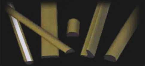
Fabric-over-foam is a compliance-driven seam interface: a compressible foam core wrapped in conductive fabric. The foam performs mechanical work by conforming to imperfect surfaces and absorbing tolerance variations. The fabric does the electrical work by forming a distributed conductive bridge once compression is applied.
FoF is typically chosen when closure force is constrained by thin doors, lightweight panels, serviceability requirements, fixed fastener spacing, or latch systems that cannot generate high loads without deforming the enclosure. That is the core fit: FoF is selected because it can maintain seam continuity inside a limited force envelope. Because FoF is compliance-driven, defining compression is mandatory; it is part of the specification.
Compression Controls Continuity, First on Day One, Then Over Time
FoF performance is determined by whether the seam maintains stable contact pressure along its full length. Average compression can look acceptable, while low-compression spans between fasteners create leakage hotspots. Door stiffness, flange flatness, latch placement, and fastener spacing decide whether compression is uniform enough for the conductive fabric to stay continuously engaged.
This is why shielding numbers cannot be treated as standalone truths. Any measured shielding effectiveness is inseparable from the compression percentage and the method of load application. Under-compression yields incomplete contact and high seam impedance. Over-compression risks damaging the foam structure, reducing rebound, and accelerating long-term pressure loss.
Time is the second half of the same problem. Foam materials relax under sustained deflection, repeated cycling, and thermal exposure. As recovery drops, contact pressure drops, contact resistance rises, and the seam becomes electrically inconsistent again. Because compression decays, long-term stability becomes the next constraint you must design for, not a footnote you discover after field failures.
Even with Compression, Seams Fail When Contact Resistance Rises
A seam can be mechanically “closed” and still be electrically poor if the interface resistance increases. Oxide formation, surface contamination, and coatings can reduce the effective contact area. In humid or corrosive environments, dissimilar conductive materials in contact can accelerate interface degradation, increasing resistance and undermining continuity even when compression remains within spec.
This is why mating-surface compatibility cannot be treated as procurement trivia. The enclosure base metal, surface finish, and operating environment determine whether the interface remains electrically healthy throughout the service life. If environmental sealing is also required, it must be explicitly specified and validated. EMI continuity and ingress protection are different performance requirements, and assuming one implies the other is a common source of misapplication.
How to Specify and Verify FoF Without Getting Misled
Two questions get confused, and they require different validation approaches.
- Material tests answer:Is this construction capable of delivering shielding when compressed under controlled conditions?
- Enclosure or seam tests answer:Will our seam, with our fastener spacing, stiffness, and compression distribution, meet the requirement?
A FoF RFQ that produces comparable quotes should include:
- seam type and perimeter geometry,
- seam length, gap range, and flatness expectations,
- available closure force or latch specification,
- target compression window or maximum allowable compression,
- frequency band driving the requirement,
- environmental exposure and service life expectations,
- mating surface materials and finishes,
- installation format preference (strip, frame, adhesive-backed, mechanical retention),
- documentation requirements, including method used, frequency sweep range, compression condition, and fixture description.
When reviewing any datasheet or report, demand the context that determines whether the number correlates to your enclosure:
- named test method,
- frequency range validated,
- compression percentage or deflection,
- how load was applied and held uniform,
- fixture description including seam representation and contact-point spacing.
If those items are missing, you do not have decision-grade data. Use material-level results to narrow options, then validate on a representative seam geometry before committing to production. The seam system passes or fails, not the gasket in isolation.
The JEMIC Method: Turning Seam Constraints into a Reliable Gasket Choice
JEMIC treats fabric-over-foam as an engineered interface rather than a commodity. We start with the seam: gap range, closure force limitations, fastener or latch geometry, and expected compression distribution. We assess mating surfaces and the environment to avoid compatibility-driven degradation. We match foam compliance to the enclosure’s force envelope, ensuring the gasket operates within a stable compression window over time. We recommend formats that reduce installation variability, including strip, frame, and custom-cut solutions designed for consistent placement.
Most importantly, we align the verification approach with the real enclosure so qualification measures seam continuity under realistic conditions, not an abstract number detached from compression and fixture assumptions. If clamp loads are constrained, FoF can be the right solution, but only when compression, compatibility, and validation are treated as the design requirements they truly are.
Ensuring the Best Quality EMI Gaskets
Fabric-over-foam EMI gaskets solve a specific problem: maintaining seam continuity when high clamp loads are not available. That only holds when compression and compression stability are defined, controlled, and matched to the enclosure mechanics. Mating-surface compatibility and the verification context determine whether test data correlate with real-world seam behavior. JEMIC builds FoF solutions around those constraints so seam performance is engineered rather than hoped for.