The Miniaturization Dilemma in Next-Generation Electronics Packaging
In modern aerospace avionics, millimeter-wave radar units, 5G telecommunications infrastructure, and high-density automotive ADAS modules, packaging engineers face an intense mechanical squeeze. As internal clock frequencies climb well into the gigahertz realm, electromagnetic compatibility (EMC) tolerances tighten dramatically. At the same time, enclosure footprints keep shrinking, leaving mounting flanges narrower than 1.5 millimeters. For hardware design teams specifying an EMI gasket, traditional sealing methods quickly reach their physical limits. Die-cut conductive elastomers, stamped metal fingerstock, and fabric-over-foam profiles are physically impossible to align and assemble into intricate multi-cavity labyrinth housings without buckling, falling out, or shorting internal circuit traces.
This miniaturization bottleneck has made Form-in-Place (FIP) conductive elastomer gasket technology the industry standard for shielding tight electronic enclosures. By dispensing automated conductive beads directly onto narrow casting ledges and machined aluminum walls, FIP eliminates mechanical assembly errors while delivering reliable electromagnetic shielding attenuation exceeding 80 to 100 dB across critical RF bands.
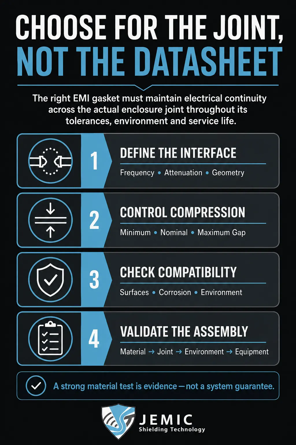 Robotic Dispensing Physics: Micro-Beads on Narrow Milled Flanges
Form-in-place technology replaces manual gasket placement with high-precision, computer-controlled XYZ dispensing robotics. A single-component or two-component conductive polymer compound—typically a silicone or fluorosilicone elastomer densely loaded with microscopic conductive filler particles—is pumped through a micro-aperture dispensing nozzle under closed-loop pressure control.
● Sub-Millimeter Flange Deposition: Robotic dispensing heads deposit continuous conductive beads onto flange ledges as narrow as 0.75 mm (0.030 inches), following complex 3D contours and multi-compartment internal compartmental walls with positioning accuracy within ±0.02 mm.
● Seamless Corner Integrity: Unlike die-cut gaskets that require bonded joints or stamped fingerstock with corner gaps, dispensed FIP beads flow continuously around acute 90-degree corners, eliminating seam leakage.
● Integrated Mechanical Adhesion: FIP formulations bond directly to bare metal, plated aluminum, or conductive conversion coatings during curing, eliminating the need for conductive pressure-sensitive adhesive (PSA) tapes that add thickness and electrical contact resistance.
Bead Geometry, Compression Dynamics, and Flange Deflection
Designing an effective FIP gasket requires balancing bead cross-sectional geometry with enclosure mechanical rigidity. Dispensing systems typically lay down either a triangular (apex) bead or a rounded hemispherical profile. Triangular profiles are generally preferred for small flanges because they require significantly lower initial closure force to achieve electrical contact, compensating for slight machining tolerances across cast aluminum lids.
The recommended design operating compression for FIP gaskets is between 20% and 35% of nominal bead height. Compressing a bead beyond 40% risks permanent compression set and can fracture the delicate conductive filler network within the elastomer. Furthermore, because conductive elastomers are virtually incompressible fluids under volume constraint, the enclosure flange must provide adequate space for lateral material bulge. If you use a groove, the cross-sectional groove volume must exceed the nominal bead volume by at least 15% to prevent hydraulic squeeze-out and lid distortion.
Conductive Filler Systems: Shielding Attenuation vs. Galvanic Risk
The electromagnetic shielding effectiveness and environmental longevity of an FIP gasket depend on the metallic filler embedded in the silicone matrix. Selecting the right filler requires balancing electrical conductivity against the risk of galvanic corrosion with the mating aluminum chassis.
| Conductive Filler Material | Typical Shielding Effectiveness (100 MHz – 10 GHz) | Volume Resistivity (Ω-cm) | Galvanic Compatibility (with Al 6061) | Primary Application Field |
| Silver-Plated Aluminum (Ag/Al) | 90 to 110 dB | 0.008 Ω-cm | Excellent; closely matched electrochemical potential | Military avionics, aerospace chassis, outdoor 5G telecom |
| Nickel-Plated Graphite (Ni/C) | 80 to 95 dB | 0.050 Ω-cm | Good; moderate galvanic potential difference | Automotive ADAS, commercial telecom, industrial electronics |
| Silver-Plated Copper (Ag/Cu) | 100 to 120 dB | 0.004 Ω-cm | Poor; severe galvanic corrosion in humid salt environments | Laboratory RF test fixtures, enclosed EMI shielded modules |
| Pure Silver (Ag) | 110 to 125 dB | 0.002 Ω-cm | Poor; high electrochemical potential difference | Specialized satellite payloads and cryogenic microwave systems |
For outdoor telecommunications enclosures and marine avionics, Silver-Plated Aluminum remains the premier filler choice. Under MIL-STD-1250 and ASTM B117 salt fog exposure, silver-plated aluminum particles minimize the galvanic potential difference between the gasket and chromate-converted aluminum housings, preventing electrolytic pitting that destroys RF shielding over time.
Thermal Cure vs. Moisture-Cure Elastomer Formulations
Manufacturing engineers must also select the optimal curing mechanism for their production environment.
● Thermal-Cure Silicones: These single-component elastomers cure in convection or infrared ovens at 250°F to 300°F (120°C to 150°C) in 30 to 60 minutes. Thermal curing achieves superior compression set resistance (<25% after 1,000 hours) and maximum physical toughness, making it ideal for high-reliability cast aluminum enclosures.
● Room Temperature Vulcanizing (RTV) Moisture-Cure: Moisture-cure silicones vulcanize through reaction with ambient atmospheric humidity over 24 hours at room temperature. They are mandatory when dispensing onto temperature-sensitive plastic enclosures, pre-populated circuit boards, or optical assemblies that cannot withstand oven bake cycles.
● UV-Curable Elastomer Systems: Emerging dual-cure UV formulations utilize high-intensity ultraviolet light to achieve rapid skinning in seconds, followed by secondary moisture curing for shadow areas, significantly accelerating high-volume electronic assembly lines.
Fastener Spacing to Eliminate High-Frequency Slot Antennas
Even the most advanced FIP bead cannot prevent RF leakage if the mating enclosure lid bows between mounting screws. At gigahertz frequencies, any gap larger than a fraction of the operating wavelength acts as an efficient slot antenna. For instance, at 10 GHz, a half-wavelength slot measures just 15 millimeters (0.6 inches); any lid deflection over that distance allows microwave radiation to leak freely.
To ensure continuous electrical contact, mechanical designers must calculate screw pitch based on lid stiffness and gasket compression force. Placing fasteners close enough to maintain a consistent 25% bead deflection across the entire perimeter ensures an unyielding Faraday barrier, preventing radiated-emissions compliance failures during FCC and CISPR chamber certifications.
Environmental Testing and MIL-DTL-83528 Qualification
Before deploying FIP conductive gaskets in mission-critical aerospace or military communication hardware, qualification testing under MIL-DTL-83528 is standard practice. Elastomer test plaques undergo accelerated heat aging, fluid immersion (jet fuel, hydraulic fluids), and severe mechanical shock testing to ensure electrical volume resistivity does not degrade over prolonged field deployment.
Furthermore, high-g vibration testing confirms that the dispensed bead maintains adhesion to the machined housing without tearing or flaking conductive particulates onto sensitive circuit boards. Maintaining elastic recovery across broad temperature swings from -55°C to +125°C guarantees uncompromised RF isolation across extreme flight profiles.
Consultative Implementation for High-Density Hardware Packaging
Integrating Form-in-Place conductive gaskets into complex electronic hardware requires early collaboration between mechanical packaging engineers, RF specialists, and dispensing experts. Evaluating bead paths, groove tolerances, and filler metallurgy during initial DFM reviews prevents costly tooling rework.
By leveraging automated FIP dispensing, hardware manufacturers achieve uncompromising electromagnetic isolation across razor-thin flanges while drastically reducing manual assembly labor. Partnering with experienced shielding specialists ensures that next-generation electronic systems pass stringent EMC compliance testing on the very first pass.